Dynamic analysis of a beam
We perform the dynamic analysis of a steel catenary riser (SCR) subject to forced top motions. We compare the results against the corresponding SIMA/RIFLEX example case. The riser consists of three segments with two different cross-sections.
NB: In two places in this script, solve is called with optional verbose=false, because this script is part of the generation of Muscade's online documentation. Setting verbose=true would be more relevant in other contexts.
using Muscade, StaticArrays, GLMakie, Muscade.Toolbox, Interpolations, CSV, DataFramesRead RIFLEX motions, tensions, bending moment and curvatures time series (verification data)
file_path = "SCR.csv"
df = CSV.read(file_path, DataFrame; delim=' ')
dynMotionX = vcat(0,df[:,"Displacement in x - direction"].-df[1,"Displacement in x - direction"],df[end,"Displacement in x - direction"]-df[1,"Displacement in x - direction"])
dynMotionZ = vcat(0,df[:,"Displacement in z - direction"].-df[1,"Displacement in z - direction"],df[end,"Displacement in z - direction"]-df[1,"Displacement in z - direction"])
dynMotionT = vcat(-10.,df[:,"x"],df[end,"x"]+100)
xMotion = linear_interpolation(dynMotionT,-dynMotionX)
zMotion = linear_interpolation(dynMotionT,dynMotionZ);
Some physical constants
const g=9.81
const ρ=1025.;
Normalized gravity field, ramping up during static analysis
@functor with() ramping_gravityField(t)= clutch(t,-9.,-5.,0.,1.,1) * SVector(0.,0.,-1.);Define parameters for cross-section 1
x1_D    = 0.429                     # Outer diameter [m]
x1_t    = 0.022                     # Thickness [m]
x1_steelArea = (x1_D-x1_t)*π*x1_t   # Pipe wall area [m^2]
x1_innerArea = (x1_D-2*x1_t)^2*π/4  # Inner area [m^2]
x1_ρₛ   = 7850.                     # Steel denstiy [kg/m^3]
x1_ρᵢ   = 200.                      # Internal fluid density [kg/m^3]
x1_EA   = 5.823e9                   # Axial stiffness [N]
x1_EI₂  = 1.209e8                   # Bending stiffness [Nm/(1/m)]
x1_EI₃  = 1.209e8                   # Bending stiffness [Nm/(1/m)]
x1_GJ   = 9.347e7                   # Torsional stiffness [Nm/(rad/m)]
x1_μ    = x1_steelArea*x1_ρₛ + x1_innerArea*x1_ρᵢ   # Mass per unit length [m]
x1_ι₁   = 0.2053^2*x1_steelArea*x1_ρₛ # Moment of inertia about x-axis per unit length [kgm²/m]
x1_w    = x1_μ*g - π*x1_D^2/4*ρ*g   # Weight per unit length [N/m]
x1_Dh    = 0.459                    # Hydrodynamic outer diameter [m]
x1_Ca₂  = 1.0 *         ρ * π*x1_Dh^2/4 # Transverse added mass coefficients [N/m/(m/s^2)]
x1_Ca₃  = 1.0 *         ρ * π*x1_Dh^2/4
x1_Cq₂  = 1.0 *   0.5 * ρ * x1_Dh   # Transverse drag coefficients [N/m/(m/s)^2]
x1_Cq₃  = 1.0 *   0.5 * ρ * x1_Dh
x1_mat         = BeamCrossSection(EA=x1_EA, EI₂=x1_EI₂, EI₃=x1_EI₃, GJ=x1_GJ, μ=x1_μ, ι₁=x1_ι₁, w=x1_w, g̃=ramping_gravityField, Ca₂=x1_Ca₂, Cq₂=x1_Cq₂, Ca₃=x1_Ca₃, Cq₃=x1_Cq₃)
BeamCrossSection{Functor{:ramping_gravityField, @NamedTuple{}}}(5.823e9, 1.209e8, 1.209e8, 9.347e7, 244.10222042282496, 9.307102957808986, 941.2020115973273, Functor{:ramping_gravityField, @NamedTuple{}}(NamedTuple()), 0.0, 0.0, 0.0, 169.60518222430625, 0.0, 235.2375, 169.60518222430625, 0.0, 235.2375)Define parameters for cross-section 2
x2_D    = 0.441                     # Outer diameter [m]
x2_t    = 0.028                     # Thickness [m]
x2_steelArea = (x2_D-x2_t)*π*x2_t   # Pipe wall area [m^2]
x2_innerArea = (x2_D-2*x2_t)^2*π/4  # Inner area [m^2]
x2_ρₛ   = 7850.                     # Steel denstiy [kg/m^3]
x2_ρᵢ   = 200.                      # Internal fluid density [kg/m^3]
x2_EA   = 7.520e9                   # Axial stiffness [N]
x2_EI₂  = 1.611e8                   # Bending stiffness [Nm/(1/m)]
x2_EI₃  = 1.611e8                   # Bending stiffness [Nm/(1/m)]
x2_GJ   = 1.245e8                   # Torsional stiffness [Nm/(rad/m)]
x2_μ    = x2_steelArea*x2_ρₛ + x2_innerArea*x2_ρᵢ    # Mass per unit length [m]
x2_ι₁   = 0.2084^2*x2_steelArea*x2_ρₛ # Moment of inertia about x-axis per unit length [kgm²/m]
x2_w    = x2_μ*g - π*x2_D^2/4*ρ*g   # Weight per unit length [N/m]
x2_Dh    = 0.471                    # Hydrodynamic outer diameter [m]
x2_Ca₂  = 1.0 *         ρ * π*x2_Dh^2/4 # Transverse added mass coefficients [N/m/(m/s^2)]
x2_Ca₃  = 1.0 *         ρ * π*x2_Dh^2/4
x2_Cq₂  = 1.0 *   0.5 * ρ * x2_Dh   # Transverse drag coefficients [N/m/(m/s)^2]
x2_Cq₃  = 1.0 *   0.5 * ρ * x2_Dh
x2_mat         = BeamCrossSection(EA=x2_EA, EI₂=x2_EI₂, EI₃=x2_EI₃, GJ=x2_GJ, μ=x2_μ, ι₁=x2_ι₁, w=x2_w, g̃=ramping_gravityField, Ca₂=x2_Ca₂, Cq₂=x2_Cq₂, Ca₃=x2_Ca₃, Cq₃=x2_Cq₃)
BeamCrossSection{Functor{:ramping_gravityField, @NamedTuple{}}}(7.52e9, 1.611e8, 1.611e8, 1.245e8, 308.46874150589946, 12.385770874447834, 1490.1889896489647, Functor{:ramping_gravityField, @NamedTuple{}}(NamedTuple()), 0.0, 0.0, 0.0, 178.58935181540963, 0.0, 241.3875, 178.58935181540963, 0.0, 241.3875)Model SCR, starting from the extremity located on seabed
nel         = [60,      30,     10] # Number of elements per segment
segLength   = [300.,    300.,   80.] # Segment lengths
xSection    = [x1_mat,  x2_mat, x1_mat]; # Cross-section type
Create Muscade model
model = Model(:CatenaryRiser);Create nodes, elements representing the SCR
topNode     = addnode!(model,[0,0,0])
nodeList, elementList, nodeCoord = MeshLine!(model, topNode, π, EulerBeam3D, xSection, segLength, nel; orient2=SVector(0.,1,0));
Fix lower extremity
[addelement!(model,Hold,[nodeList[1][1]] ;field) for field∈[:t1,:t2,:t3,:r1]];Loading procedure for the static analysis is as follows
- start by elongating the line to create geometric stiffness
- apply the weight (can be done rapidly)
- move the end of the line to the prescribed displacement
- contact forces
Define the prescribed end displacements of the top extremity
@functor with(xMotion) horizMove(x,t)= SVector( x[1]-(1.0 - clutch(t,-10.,0,0.,1.,3)*181.0 + xMotion(t)) )
@functor with(zMotion) vertMove(x,t) = SVector( x[1]-(      clutch(t,-10.,0,0.,1.,3)*303.1 + zMotion(t)) )
addelement!(model,DofConstraint,[nodeList[3][end]]; λclass=:X, xinod=(1,),xfield=(:t1,), λinod=(1,),λfield=(:λt1,), gap=horizMove, mode=Muscade.equal)
addelement!(model,DofConstraint,[nodeList[3][end]]; λclass=:X, xinod=(1,),xfield=(:t3,), λinod=(1,),λfield=(:λt3,), gap=vertMove , mode=Muscade.equal);
Contact elements for the bottom segment
[addelement!(model,SoilContact,[nodeList[1][idxNod]],z₀=0.,Kh=1.0e3,Kv=1.0e4,Ch=0.,Cv=0.) for idxNod = 1:length(nodeList[1])];Run the static analysis
initialstate    = initialize!(model);
staticLoadSteps = (-10:.2:0)*1.
nStaticLoadSteps = length(staticLoadSteps)
staticStates           = solve(SweepX{0};initialstate,time=staticLoadSteps,verbose=false,maxΔx=1e-6,maxiter=100);
Plot the static analysis sequence
fig      = Figure(size = (1000,1000))
ax = Axis3(fig[1,1])
for stateIdx ∈ 1:nStaticLoadSteps
    draw!(ax,staticStates[stateIdx],EulerBeam3D=(;style=:shape))
end
currentDir = @__DIR__
if occursin("build", currentDir)
    save(normpath(joinpath(currentDir,"..","src","assets","staticEquilibriumSCR.png")),fig)
elseif occursin("examples", currentDir)
    save(normpath(joinpath(currentDir,"staticEquilibriumSCR.png")),fig)
end
Run the dynamic analysis
dynamicLoadSteps = (0.1:0.3:300)*1.0
nDynamicLoadSteps = length(dynamicLoadSteps)
dynamicStates          = solve(SweepX{2};
    initialstate=staticStates[nStaticLoadSteps],
    time=dynamicLoadSteps,
    verbose=false,
    maxΔx=1e-5);
Retrieve axial force at top location
req = @request gp(resultants(fᵢ))
out = getresult(dynamicStates,req,[elementList[end]])
Fgp1_ = [ out[idxEl].gp[1][:resultants][:fᵢ] for idxEl ∈ 1:size(out,2)];
Retrieve bending moments near touch down point
req = @request gp(resultants(mᵢ))
out = getresult(dynamicStates,req,[elementList[64]])
Mgp1_ = [ out[idxEl].gp[1][:resultants][:mᵢ] for idxEl ∈ 1:size(out,2)];
Retrieve curvature near touch down point
req = @request gp(κgp)
out = getresult(dynamicStates,req,[elementList[64]])
κgp1_ = [ out[idxEl].gp[1].κgp[1] for idxEl ∈ 1:size(out,2)];
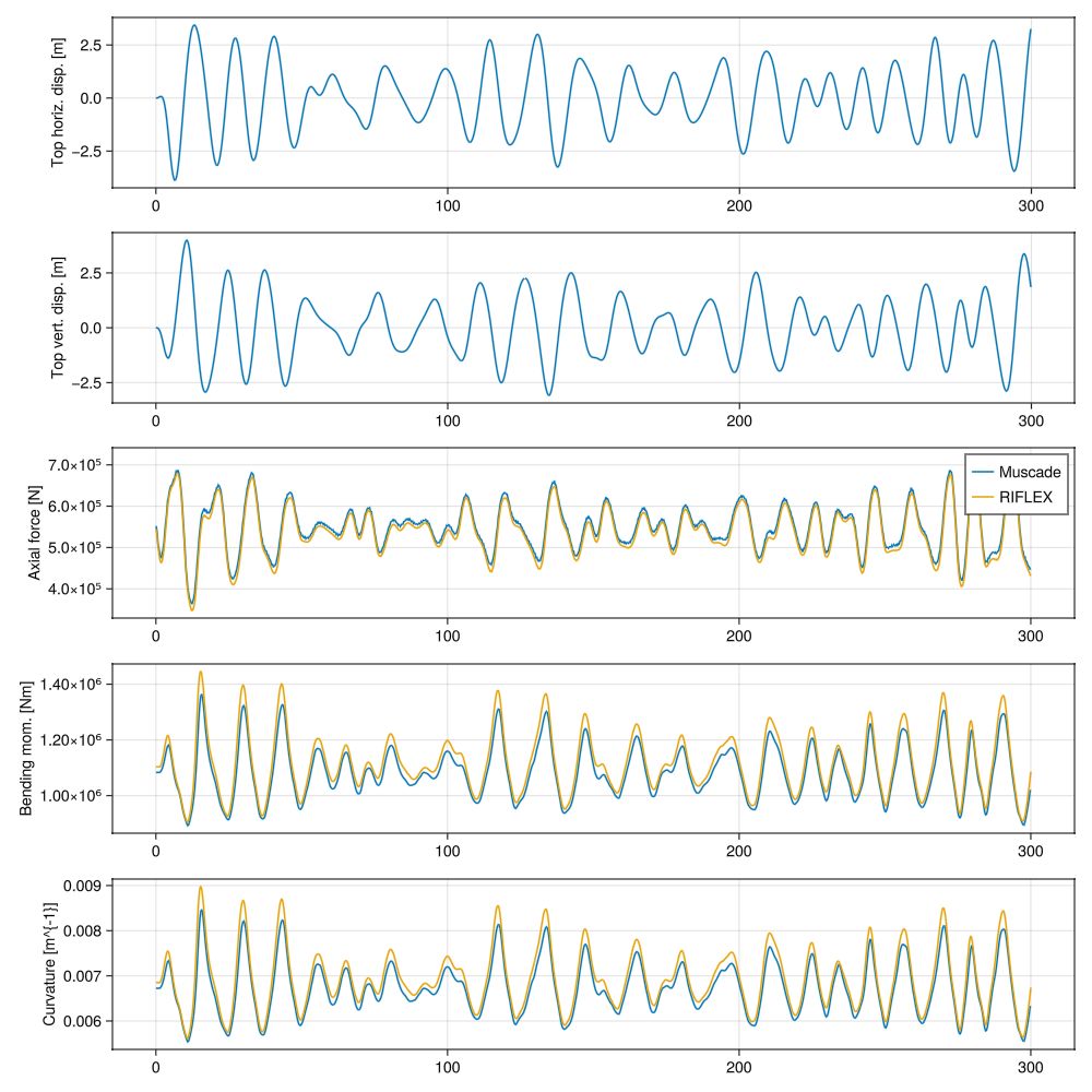
Plot comparison between Muscade and RIFLEX results.
fig2      = Figure(size = (1000,1000))
ax1 = Axis(fig2[1, 1],ylabel="Top horiz. disp. [m]")
lines!(ax1,dynamicLoadSteps,xMotion(dynamicLoadSteps))
ax2 = Axis(fig2[2, 1],ylabel="Top vert. disp. [m]")
lines!(ax2,dynamicLoadSteps,zMotion(dynamicLoadSteps))
ax3 = Axis(fig2[3, 1],ylabel="Axial force [N]")
lines!(ax3, dynamicLoadSteps, Fgp1_,                            label="Muscade")
lines!(ax3, df[:,"x"],df[:,"Axial force"],                      label="RIFLEX")
axislegend()
ax4 = Axis(fig2[4, 1],ylabel="Bending mom. [Nm]")
lines!(ax4, dynamicLoadSteps, getindex.(Mgp1_,3),               label="Muscade")
lines!(ax4, df[:,"x"],df[:,"Mom. about local y-axis, end 1"],   label="RIFLEX")
ax5 = Axis(fig2[5, 1],ylabel="Curvature [m^{-1}]")
lines!(ax5, dynamicLoadSteps, getindex.(κgp1_,3),               label="Muscade")
lines!(ax5, df[:,"x"],df[:,"Curvature about local y-axis, end 1"], label="RIFLEX")
if occursin("build", currentDir)
    save(normpath(joinpath(currentDir,"..","src","assets","dynamicAnalysisSCR.png")),fig2)
elseif occursin("examples", currentDir)
    save(normpath(joinpath(currentDir,"dynamicAnalysisSCR.png")),fig2)
end
Minor discrepancies might be due to the fact that loads are extracted at Gauss points in Muscade, while they are extracted at nodes in RIFLEX.
This page was generated using Literate.jl.